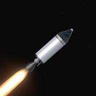
Engineering notes / The systems behind the sandbox
A small game.
A lot going on.
The interesting part is what happens when the systems meet. A moving arm changes your balance. A tether turns your payload. A heat shield protects the shape behind it. Here is how the pieces fit together.
01 / The flight engine
One world.
Two ways to move.
Rocket Foundry has its own physics engine, written in C#. Positions, velocities, orbital calculations, and contacts use double precision. Godot draws the world and handles input; the game's simulation decides where everything actually is.
In clean vacuum, a coasting vessel follows an exact two-body orbit. Add thrust, air resistance, a parachute, or contact with the ground, and the simulator integrates those forces in small steps. Flight and map views read the same state.
Solve the orbit.
Keplerian propagation
Step the forces.
Numerical integration
Go deeper: precision, warp, and the rest of your fleet
The rendering origin follows the active craft, so the graphics engine works with nearby coordinates even when the simulation is millions of kilometres from the Sun. Moving the camera never moves the physics.
Time warp advances simulation time, rather than speeding up Godot. Clean conic orbits can take large time steps without accumulating ordinary integration drift. Active powered flight and physical interactions use a lower warp ceiling. Background craft remain part of the world, with explicit rules for coasting, atmospheric encounters, and supported rest.
This is a two-dimensional, patched-conic model: each vessel has one primary gravitational body at a time. It is not an N-body gravity simulation, and high warp does not integrate every distant interaction at full resolution.
02 / The hot part
The glow has
a reason.
Atmospheric entry starts with speed and air density. A shared heating model drives luminous plasma and persistent scorching. The windward silhouette tells the thermal system which parts actually face the flow.
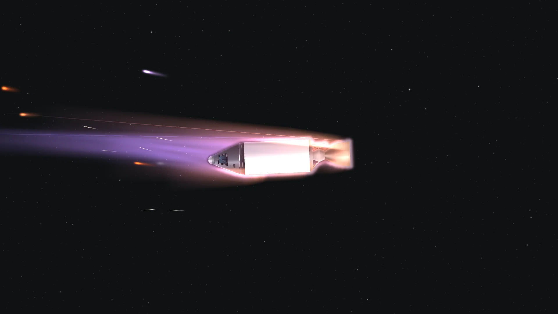
Illustration of the model's speed³ term, not a live flight prediction. In flight, density and exposed area change too.
Go deeper: from the hull silhouette to permanent scorch
The model uses a Sutton-Graves approximation: stagnation heat flux grows with the square root of density and the cube of speed. Exposed fractions receive heating, while sheltered surfaces stay cleaner. Incoming direction is recorded in each part's own frame, so scorch remains attached to the correct side after a rotation or separation.
The visual system follows the actual visible hull, including moving parts and gaps. A surface-distance field supports the glowing skin; flow-aligned ribbons form the downstream sheath and wake. The shape can change when you move a joint, open a bay, or lose a part.
Scorch survives save/load, staging, docking, and rewind. Atmospheric palettes are also editable per body. These are efficient game approximations, not computational fluid dynamics or a chemistry solver.
03 / The builder and part system
A machine made
of machines.
The builder is a grid, but your flying craft is a graph: rigid sections joined by hinges, docking connections, welds, or capture bonds. Those connections determine what moves together and what becomes a separate vessel.
That makes a folding arm, a docked station, and a multi-stage rocket different arrangements of the same structural system. Fuel, electricity, mass, balance, and exposed shape follow the craft you actually assembled.
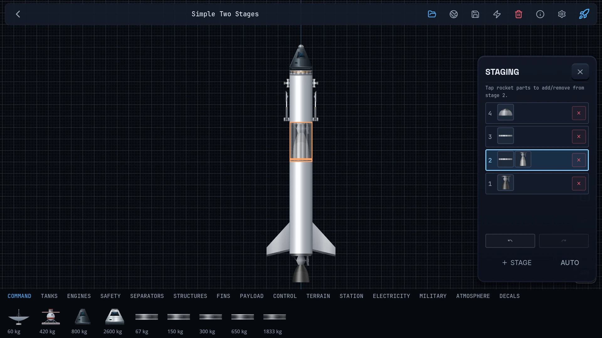
Go deeper: a docking connection is more than a parent node
Docking records a measured connection between live sections. Undocking removes that bond and checks what remains connected. A station ring with a second route between two sections stays joined when only one connection opens. Splits preserve the surviving parts' positions instead of snapping them back to an old builder grid.
A shared posed geometry feeds rendering, contact, mass properties, windward exposure, and hit testing. Swing an articulated assembly and the simulation uses the new shape and centre of mass.
Sections are rigid and joints have explicit motion. This is not a soft-body flexing model for every tank and strut.
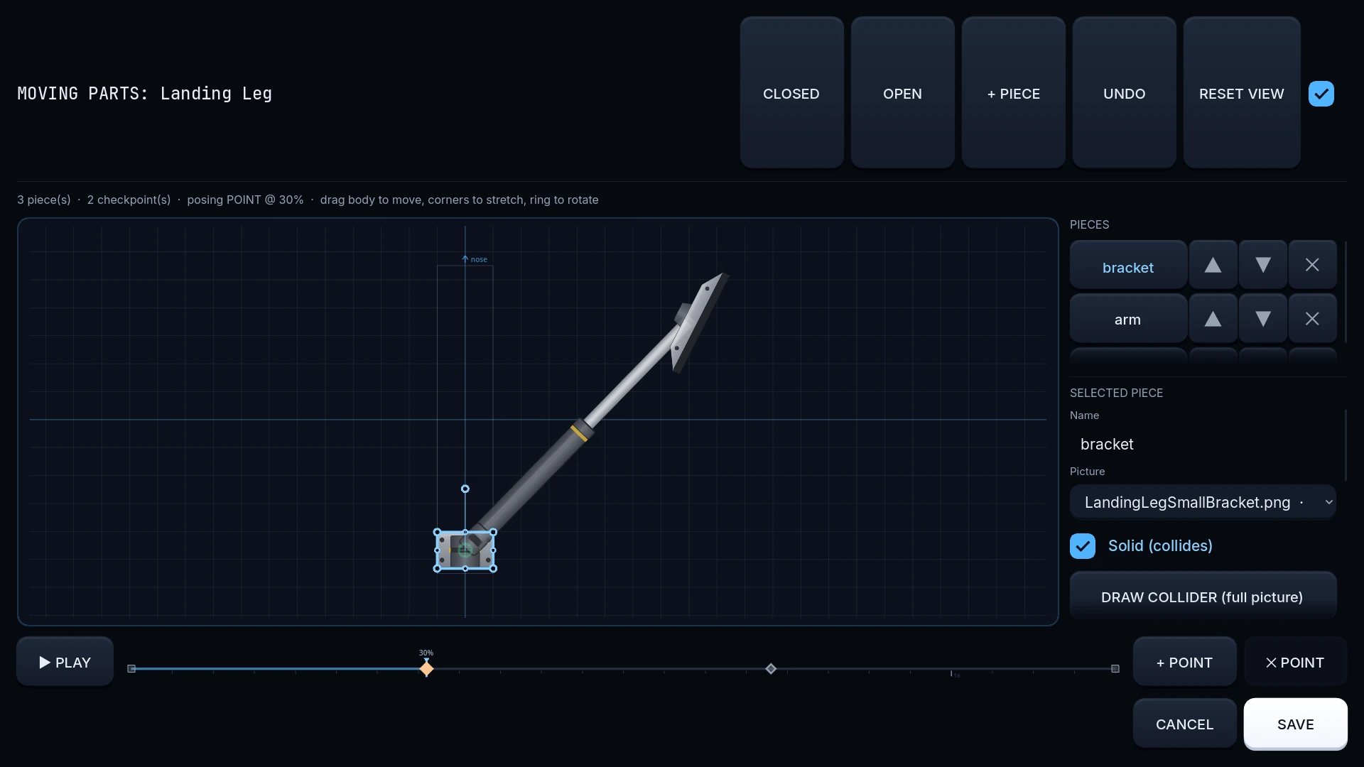
Go deeper: create parts, not just paint jobs
A part definition combines behavior blocks: engines, tanks, batteries, solar panels, wheels, RCS, parachutes, hinges, grabbers, drills, ropes, winches, and more. The mod editor exposes the corresponding properties, alongside artwork, collision geometry, and centre of mass.
The moving-parts editor authors deployable artwork and animation. The builder adds per-instance resizing, paint, and decals. You can create a new mechanism and package its content as a mod without rebuilding the game.
Worlds retain the exact versions of the mod content they use. Editing a library mod does not silently rewrite the parts and planets inside every saved Sandbox.
04 / Ropes and powered winches
Pull on something.
Feel it pull back.
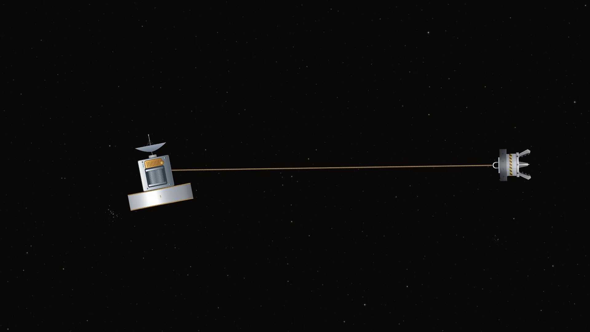
A tether connects actual attachment points on two vessels. Slack rope applies no pulling impulse. When the cable becomes taut, both craft react. Pull away from the centre of mass and that force can rotate the payload.
A powered winch can reel in, pay out, hold, or detach. Its motor draws from the connected battery network. Low charge limits it; overload stalls it. A blackout stops the motor while the passive brake retains cable length.
Force has a budget.
Power and load limit reel speed.
Both ends react.
Tension produces force and torque.
Go deeper: a constraint with a motor, not a teleport
The rope solver enforces maximum anchor separation with equal-and-opposite linear and angular impulses. Winching removes available slack, then applies a power- and force-limited pull. It does not simply shorten a taut cable and snap the cargo to a new position.
Grabbed payloads contribute their mass and rotational inertia to the pull. Surviving cable endpoints are remapped through docking, staging, and breakup. Length and motor commands are saved with the world.
The force model is a massless, two-end constraint. The drawn slack strand can settle against nearby surfaces, but full rope wrapping, self-collision, and snapping are not simulated.
05 / Body Studio
Build the place
you want to land.
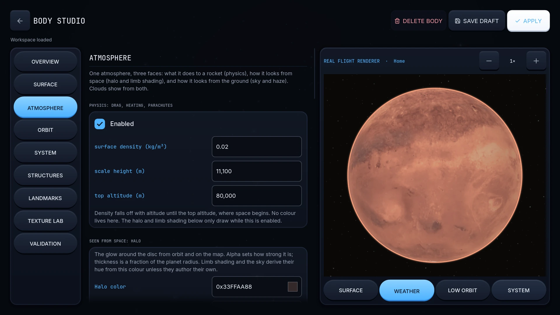
Create a star system, reshape a moon, or give a planet a new atmosphere. Body Studio brings physical properties, appearance, terrain, water, clouds, haze, rings, surface plumes, structures, and landmarks into one editor.
The preview uses the normal flight renderer. Inspect a surface, look through the atmosphere, or pull back to low orbit. The system and landmark views use the normal map, too.
Go deeper: the editor and the world speak the same language
Body Studio composes the base catalog and selected preview mods, then stores the fields you change as sparse overrides. Editing a color does not require cloning every property of a planet.
Artist pictures, close-up surface textures, and water maps connect appearance to world geometry. You can place visible structures with optional collision and launch behavior, or add image-free map labels as landmarks.
The same catalog validator checks missing parents, duplicate IDs, and orbital parent cycles before applying the result. Custom systems can start from a star and home world; they do not require deleting the stock catalog one body at a time.
06 / Terrain, water, and exploration
The ground is
part of the machine.
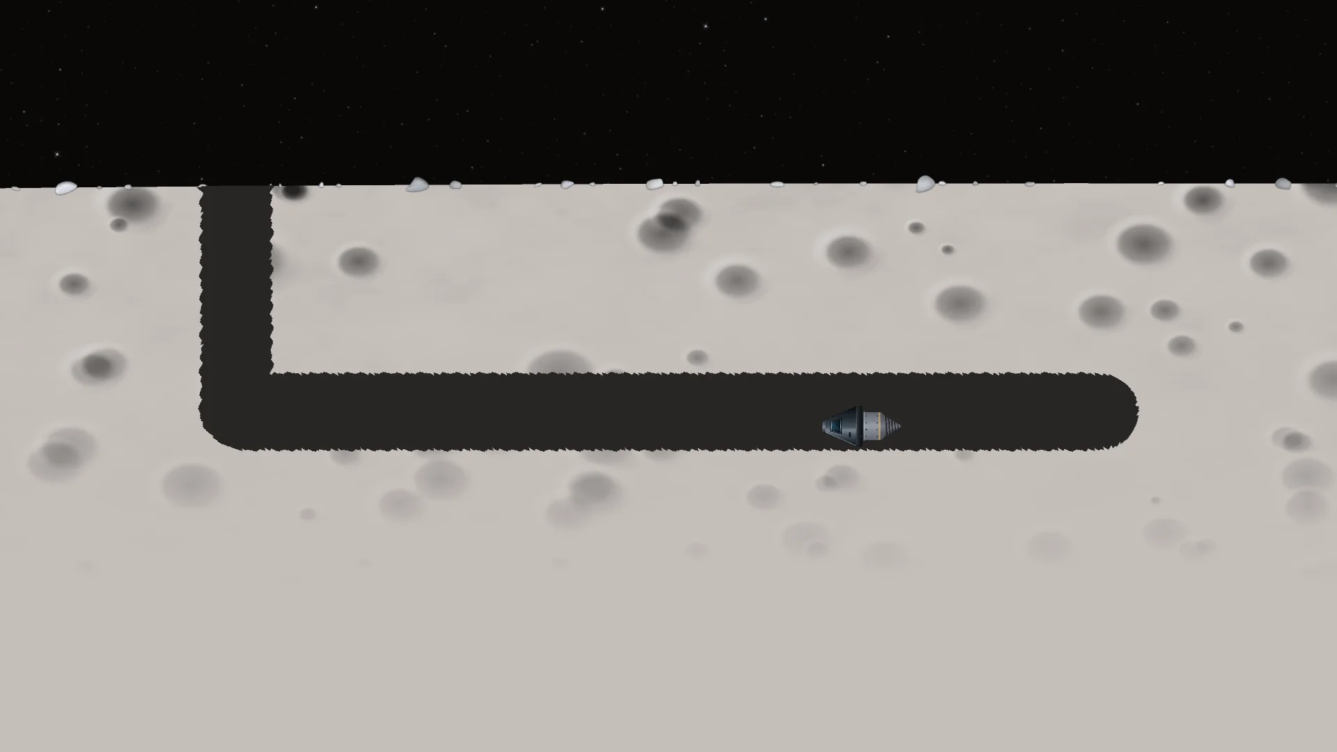
A powered drill cuts in the direction it points. Drive it sideways for a trench or a roofed tunnel. Aim downward for a shaft. The terrain system can represent overhangs, intersecting passages, and caves at different levels.
On water, buoyancy follows submerged hull geometry. Wheels use suspension and traction at their contact points. Parachutes have a staged deployment and suspension model. These systems give rovers, floating craft, and recovery vehicles something real to work against.
Go deeper: terrain is not limited to one height per angle
Excavation changes a two-dimensional material field. Derived boundaries are shared by collision queries and the terrain cut geometry. An empty cell can sit underneath solid ground, which is what makes a roofed tunnel possible.
Water displacement measures the craft's actual submerged geometry instead of floating its bounding box at an assumed depth. The same hull can behave differently as its orientation and load change.
Water is a buoyancy and contact model, not a general fluid solver. Excavating a tunnel does not currently simulate water flooding into the new void.
07 / Mission Lab
Write the plan.
Let the craft run it.
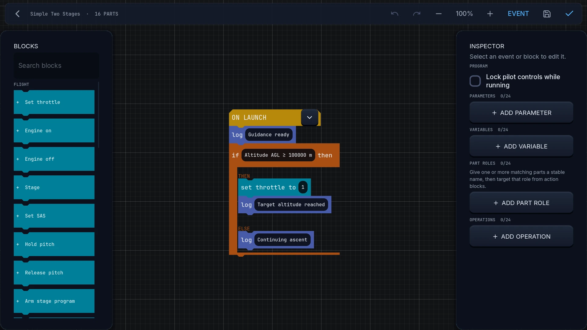
Mission Lab connects flight conditions to actions. Organize a program into phases, react to events, stage parts, and run guidance tasks. Automation goes through the simulator's normal input path, so it has to fly the same craft you do.
Programs follow their vessel. A flight program can continue on its bound craft while you inspect another one, and supported separation handoffs can give the next section its own instructions.
Go deeper: automation that survives the rest of the sandbox
The runner tracks phase progress, triggered rules, event latches, and active guidance tasks. Its state participates in save/load and rewind, rather than living only in the editor window.
Known upcoming triggers guard time warp so a large step does not jump straight past an event. An automated vessel also stays protected from background suspension. The automation system has bounded actions and phases; it is not arbitrary external code running inside your game.
08 / Three world scales
Smaller distances.
Full-size ideas.
Each world chooses 1:20, 1:10, or 1:1 celestial scale. Your rocket's dimensions, mass, thrust, and propellant stay the same. The planets and orbital distances change, while surface gravity is preserved.
| Scale | Earth radius | Vehicle size |
|---|---|---|
| 1:20 | 318.55 km | Unchanged |
| 1:10 | 637.1 km | Unchanged |
| 1:1 | 6,371 km | Unchanged |
Go deeper: why compact worlds need different engineering
For a celestial length factor s, radii and orbital distances scale by s. The gravitational parameter scales by s², keeping surface gravity constant. At corresponding orbits, speed and period scale by √s. Your vehicle keeps its thrust-to-weight ratio but needs less orbital energy.
Atmospheres and entry effects receive separate compact-scale tuning. The system preserves a recognizable re-entry challenge and visible plasma instead of uniformly shrinking every atmospheric layer or treating compact orbital speed as a gentle local descent.
Choose a scale when creating a world. It is part of that world's simulation, not a zoom control.
Your next idea deserves a launchpad
Let's see if it flies.
Get the beta, trade blueprints, and help shape what we build next.
Enter the foundry